Introduction
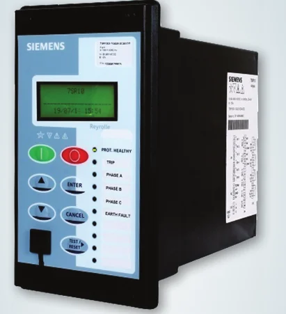
Overcurrent relays are critical components in electrical protection systems, ensuring equipment safety from excessive currents that could cause damage or faults. These relays come in two primary types: instantaneous overcurrent (ANSI 50) and time overcurrent (ANSI 51). Understanding overcurrent relay settings is essential for optimizing protection and coordination within power systems. In this article, we delve into the intricacies of overcurrent relay settings, exploring their configurations and coordination to enhance system reliability and efficiency.

Table of Contents
Instantaneous Overcurrent Relay (ANSI 50)
An instantaneous overcurrent relay operates without any intentional time delay when the current exceeds a predetermined level. This is typically used to protect equipment from short circuits or other conditions that require immediate disconnection.
Time Overcurrent Relay (ANSI 51)
A time overcurrent relay operates with a delay that varies inversely with the magnitude of the current. This delay allows for discrimination between fault levels and ensures that the relay closest to the fault operates first, thereby maintaining coordination in the protection system.
Overcurrent Relay Settings and Coordination

Overcurrent relay settings of 3 MVA 33/0.433 kV, Dyn11 Transformer Example :
For a practical example, consider a 3 MVA transformer with a primary voltage of 33 kV and a secondary voltage of 0.433 kV. The Current Transformer (CT) ratio is 1250/1 then what will be Overcurrent relay settings:
Read our articles:
Comprehensive Guide to Protective Relays in Electrical Power Systems
Instantaneous Overcurrent Relay (ANSI 50) Settings
For the instantaneous overcurrent relay setting is defined as:
- Set Point: 0.34 x In (where In = CT primary current rating)
- In: 1250 A (CT primary rating)
Thus, the relay will trip if the current exceeds: 0.34×1250 A=425 A
- Delay: 0.05 seconds
Time Overcurrent Relay (ANSI 51) Settings
For the time overcurrent relay setting is:
- Set Point: 0.05 x In (where In = CT primary current rating)
- In: 1250 A
Thus, the relay will trip if the current exceeds 0.05×1250 A=62.5 A
- Time Multiplier Setting (TMS): 0.5
- Time-Current Curve : Very Inverse (VI)
Time-Current Curves
The operation of the time overcurrent relay is defined by time-current characteristics curves, which determine how long the relay will take to trip for a given multiple of the set current. Commonly used curves include:
Types of Time-Current Curves
- Normal Inverse (NI):
- Used where coordination with downstream devices is essential.
- Provides moderate tripping speed for moderate overcurrent levels.
- Very Inverse (VI):
- More sensitive to higher overcurrent levels.
- Used where greater discrimination is needed for varying fault conditions, such as near the transformer secondary side.
- Extremely Inverse (EI):
- Highly sensitive to overcurrent, with very fast tripping at high fault currents.
- Suitable for areas with fluctuating load conditions.
- Long-Time Inverse (LTI):
- Provides a long delay for overcurrent protection.
Suitable for applications where overcurrent might be permissible for short durations.
Read our articles :
Example with Normal Inverse time Curve

Example with Very Inverse time Curve

Setting Sensitivity
To ensure maximum sensitivity, the relay settings should be configured based on the characteristics of the power system and the coordination with other protective devices. For instance, the TMS should be set lower in regions where quick fault clearance is critical, such as near sensitive equipment. Conversely, in areas where coordination with multiple devices is necessary, a higher TMS may be suitable to prevent unnecessary tripping.

Time Multiplier Setting (TMS) and Plug Multiplier Setting (PMS)
- Plug Multiplier Setting (PMS): This setting determines the current setting of the relay. It is typically a multiple of the relay’s rated current.
- Time Multiplier Setting (TMS): This setting adjusts the time delay of the relay. A lower TMS results in a faster response, while a higher TMS increases the delay.

Conclusion
Overcurrent relay settings (50/51) are essential for the protection of electrical power systems, providing both instantaneous and time-delayed responses to overcurrent conditions. By carefully setting the PMS and TMS and selecting the appropriate time-current characteristic curve, system operators can ensure effective and reliable protection for transformers and other critical equipment
Read our articles :
Comprehensive Guide to Protective Relays in Electrical Power Systems

Pingback: Comprehensive Guide to Protective Relays in Electrical Power Systems -
Pingback: Static Excitation Systems: Operation and Applications -