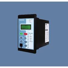
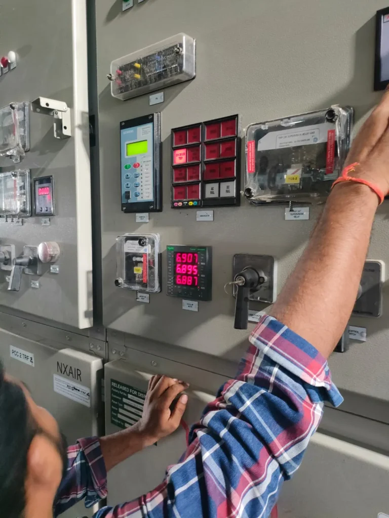
Protective relays are critical devices that ensure the safe and reliable operation of power systems by detecting abnormalities and initiating protective actions. In this article, we will explore various types of protective relays in Electrical Power Systems, with a specific focus on generator protection, along with their ANSI codes, applications, and other relevant information.
Table of Contents
Introduction to Protective Relays in Electrical Power Systems
Protective relays serve as the first line of defense in power systems, detecting faults and abnormal conditions to prevent equipment damage and maintain system reliability. The selection of the appropriate relay depends on the specific application and the nature of the protection required.

Types of Protective Relays
Protective relays are categorized based on the type of fault or abnormal condition they detect. This section delves into different types of relays, their applications, installation locations, ANSI codes, and practical use cases.
1. Current Relays

a) Overcurrent Relays (ANSI Codes 50/51)
- Application: Protects against overcurrent conditions resulting from short circuits, ground faults, or abnormal operating conditions.
- Operation: Initiates a trip signal when current exceeds a preset level.
- Installation: Typically installed in feeders, transformers, and generator circuits.
- Example Use Case: Protecting a feeder line from overcurrent due to short circuit.
b) Earth Fault Relays (ANSI Codes 50N/51N or 50G/51G)
- Application: Detects earth fault currents in grounded systems.
- Operation: Monitors residual current or direct ground current.
- Installation: Commonly used in transformers, generators, and feeder circuits.
- Example Use Case: Detecting ground faults in a transformer to prevent insulation damage.
c) Breaker Failure Relay (ANSI Code 50BF)
- Application: Detects failure of a circuit breaker to open during a fault condition.
- Operation: Initiates backup tripping of adjacent breakers.
- Installation: Installed alongside primary protection relays in circuit breaker panels.
- Example Use Case: Ensuring fault isolation when a breaker fails to operate.
d) Negative Sequence/Unbalance Relay (ANSI Code 46)
- Application: Detects unbalanced conditions in the system.
- Operation: Measures negative sequence components of current or voltage.
- Installation: Typically used in generators and large motors.
- Example Use Case: Protecting a generator from unbalanced load conditions causing overheating.
e) Thermal Overload Relay (ANSI Code 49RMS)
- Application: Protects against excessive thermal stress.
- Operation: Uses a thermal model to predict heating effects based on RMS current.
- Installation: Installed in motors and transformers.
- Example Use Case: Monitoring motor temperature to prevent overheating and insulation damage.
2. Voltage Relays

a) Overvoltage Relays (ANSI Code 59)
- Application: Protects against overvoltage conditions.
- Operation: Monitors voltage levels and initiates a trip when they exceed a preset threshold.
- Installation: Used in generators, transformers, and distribution systems.
- Example Use Case: Preventing overvoltage damage in a generator during transient conditions.
b) Undervoltage Relays (ANSI Code 27)
- Application: Protects against undervoltage conditions.
- Operation: Initiates a trip signal when voltage falls below a preset level.
- Installation: Commonly used in motors and generators.
- Example Use Case: Protecting motors from damage due to insufficient voltage supply.
c) Neutral Voltage Displacement Relay (ANSI Code 59N)
- Application: Detects displacement of the neutral voltage.
- Operation: Monitors the voltage of the neutral point relative to ground.
- Installation: Used in impedance-grounded systems.
- Example Use Case: Identifying ground faults in an impedance-grounded generator system.
3. Frequency Relays
a) Overfrequency Relays (ANSI Code 81H)
- Application: Protects against high-frequency conditions.
- Operation: Monitors system frequency and initiates a trip when frequency exceeds a preset level.
- Installation: Used in generators and grid protection schemes.
- Example Use Case: Preventing generator damage due to excessive rotational speed.
b) Underfrequency Relays (ANSI Code 81L)
- Application: Protects against low-frequency conditions.
- Operation: Initiates a trip when frequency falls below a preset threshold.
- Installation: Common in load-shedding schemes to prevent system collapse.
- Example Use Case: Isolating non-essential loads during a frequency dip to stabilize the system
c) Rate of Change of Frequency Relay (ANSI Code 81R)
- Application: To detect rapid changes in system frequency, which can indicate disturbances such as sudden loss of generation or load.
- How It Works: The relay measures the rate at which the frequency changes over a short period. If the rate exceeds a preset threshold, it sends a trip signal to disconnect the affected part of the system or to initiate corrective actions.
- Installation: Typically used in generators, grid interconnections, and large industrial plants.
- Example Use Case: In a large power plant, a sudden loss of a major generator can cause a rapid frequency drop. The 81R relays in Electrical Power Systems detects this rate of change and initiates load shedding or other protective actions to stabilize the system.
4. Directional Relays
a) Directional Overcurrent Relay (ANSI Code 67)
- Application: Detects overcurrent conditions in a specified direction.
- Operation: Measures current direction and magnitude.
- Installation: Used in systems with multiple power sources, like interconnecting feeders.
- Example Use Case: Ensuring correct fault isolation in a complex distribution network.
b) Directional Earth Fault Relay (ANSI Code 67N/67NC)
- Application: Detects earth faults in a specified direction.
- Operation: Operates based on the direction and magnitude of earth fault current.
- Installation: Commonly used in grounded distribution systems.
- Example Use Case: Isolating ground faults in a system with multiple grounding points.
Generator Protection Relays in Electrical Power Systems
Generators are critical components of power systems, requiring specific protection to maintain stability and reliability. Generator protection relays incorporate several functions to safeguard against various faults and abnormal conditions.
1. Differential Protection (ANSI Code 87G)
- Function: Protects against internal phase-to-phase and phase-to-ground faults.
- Operation: Compares current entering and leaving the generator windings.
- Installation: Essential for all generators, particularly in power plants.
- Example Use Case: Detecting a winding short circuit in a large hydroelectric generator.
2. Overcurrent Protection (ANSI Code 50/51G)
- Function: Protects against overcurrent conditions.
- Operation: Monitors current levels in the generator windings.
- Installation: Used in generator circuits to prevent damage from excessive currents.
Example Use Case: Preventing generator damage due to overloads in a thermal power plant.
3. Loss of Excitation Protection (ANSI Code 40G)
- Function: Protects against loss of excitation.
- Operation: Monitors generator field current or voltage.
- Installation: Crucial for synchronous generators.
- Example Use Case: Detecting loss of excitation in a coal-fired power plant generator.
4. Reverse Power Protection (ANSI Code 32G)
- Function: Protects against reverse power flow.
- Operation: Monitors power flow direction.
- Installation: Used in all generators connected to the grid.
- Example Use Case: Preventing a generator from operating as a motor in a combined cycle power plant.
5. Overvoltage Protection (ANSI Code 59G)
- Function: Protects against overvoltage conditions.
- Operation: Monitors generator voltage levels.
- Installation: Common in large generators and grid-connected systems.
- Example Use Case: Protecting a generator from overvoltage during load rejection events.
6. Undervoltage Protection (ANSI Code 27G)
- Function: Protects against undervoltage conditions.
- Operation: Monitors generator voltage levels.
- Installation: Used in generator control and protection schemes.
- Example Use Case: Preventing generator damage from low voltage during startup.
7. Earth Fault Protection (ANSI Code 64G)
- Function: Detects ground faults.
- Operation: Initiates a trip signal when a ground fault is detected.
- Installation: Critical for all grounded generator systems.
- Example Use Case: Detecting a ground fault in the stator winding of a wind turbine generator.
Conclusion
Protective relays in Electrical Power Systems are indispensable in modern systems, providing critical protection for generators, transformers, motors, and other equipment. Understanding the types, applications, and specific relay functions is essential for ensuring the safety and reliability of power systems. By employing the appropriate protective relays, utilities and industries can effectively prevent equipment damage, enhance system stability, and maintain uninterrupted power supply.

Pingback: Overcurrent Relay (50/51) Settings and Coordination -